Subscribe To Newsletter
C5 Series CMOS Cameras C5 camera series is designed to accommodate the latest generation of extremely large Sony IMX CMOS sensor with 100 MPx resolution and diagonal dimension up to 67 mm. Many of the used sensor properties share the exceptional features of the sensors used in the C3 series, including the 3.76 μm pixel size with the full-well capacity exceeding 50 ke-, very high quantum efficiency thanks to back-illuminated design and very low dark current. C5 sensors also offer 16 bit digitization, perfectly linear response to light and exceptionally low read noise. Despite very large sensors, the C5 camera head dimensions are the same like the Enhanced Cooling variants of the C3 and C4 series. All these features make C5 cameras the ultimate devices for both aesthetic astro-photography as well as astronomical research.
C5 Series CMOS Cameras
| C5 camera series is designed to accommodate the latest generation of extremely large Sony IMX CMOS sensors with 100 MPx resolution and diagonal dimension up to 67 mm. Many of the used sensor properties share the exceptional features of the sensors used in the C3 series, including the 3.76 μm pixel size with the full-well capacity exceeding 50 ke-, very high quantum efficiency thanks to back-illuminated design and very low dark current. C5 sensors also offer 16 bit digitization, perfectly linear response to light and exceptionally low read noise. Despite very large sensors, the C5 camera head dimensions are the same like the Enhanced Cooling variants of the C3 and C4 series. All these features make C5 cameras the ultimate devices for both aesthetic astro-photography as well as astronomical research. |
|
C5 cameras look reveal the same time-proven design school of the C3 and C4 series in both outer shape and also internal construction. C5 camera head front cross-section is the same like the in the case of C3 and C4 series, although the used sensors are much larger. C5 head thickness corresponds to the thickness of the Enhanced Cooling versions of the earlier models. But still, C5 series feature completely redesigned air cooling — more powerful and also quieter than even the EC variants of the C3 and C4. Also, the supplied AC/DC brick power adapter is more powerful and employs more robust power plug. Usage of large sensors required completely new design of the telescope interface and the C5 series offers M68 × 1 threaded adapter only on the smaller 100 MPx C5 variant. Large 150 MPx version of the C5 standardizes on the M85 × 1 thread on the tiltable adapter. Like in the case of the C4 series, the internal filter wheel is not an option, external filter wheels are necessary and the C5 camera are equipped to control new EFW-5XL series of filter wheels. Huge sensors require huge 65 × 65 mm square filters and EFW-5XL-5 is designed for five such filters. The EFW-5XL-7 filter wheels for seven smaller 50 × 50 mm square filters are available for 100 MPx C5 variant with smaller sensor. Rich software and driver support allow usage of C5 camera without necessity to invest into any 3rd party software package thanks to included free SIPS software package. However, ASCOM (for Windows) and INDI (for Linux) drivers and Linux driver libraries are shipped with the camera, provide the way to integrate C5 camera with broad variety of camera control programs. The C5 cameras are designed to work in cooperation with a host Personal Computer (PC). As opposite to digital still cameras, which are operated independently on the computer, the scientific cooled cameras usually require computer for operation control, image download, processing and storage etc. To operate the camera, you need a computer which:
C5 cameras are designed to be attached to host PC through very fast USB 3.0 port. While the C5 cameras remain compatible with older (and slower) USB 2.0 interface, image download time is significantly longer. Alternatively, it is possible to use the Moravian Camera Ethernet Adapter device. This device can connect up to four Cx (and CCD based Gx) cameras of any type (not only C5, but also C1, C2, C3 and C4) and offers 1 Gbps and 10/100 Mbps Ethernet interface for direct connection to the host PC. Because the PC then uses TCP/IP protocol to communicate with the cameras, it is possible to insert WiFi adapter or other networking device to the communication path. Hint: Please note that the USB standard allows usage of cable no longer than approx. 5 meters and USB 3.0 cables are even shorter to achieve very fast transfer speeds. On the other side, the TCP/IP communication protocol used to connect the camera over the Ethernet adapter is routable, so the distance between camera setup and the host PC is virtually unlimited. Download speed is naturally significantly slower when camera is attached over Ethernet adapter, especially when compared with direct USB 3 connection. The camera must be connected to some optical system (e.g. the telescope) to capture images. As the C5 cameras offer really large sensors with 67 mm (150 MPx version) and 55 mm (100 MPx version) diagonals, optical system must be capable to cover such large field of view. The camera is designed for long exposures, necessary to acquire the light from faint objects. If you plan to use the camera with the telescope, make sure the whole telescope/mount setup is capable to track the target object smoothly during long exposures. C5 Camera OverviewC5 camera head is designed to be used with or without external filter wheel. The EFW-5XL external filter wheel with 50 × 50 mm filters is suitable for C5A-100M camera only, large sensor C5A-150M model needs EFW-5XL external filter wheel, designed for 65 × 65 mm filters. Schematic diagram of C5 camera system Components of C5 Camera system include:
CMOS Sensor and Camera ElectronicsC5 cameras are equipped with Sony IMX rolling shutter back-illuminated CMOS detectors with 3.76 × 3.76 μm square pixels. Despite the relatively small pixel size, the full-well capacity over 50 ke- rivals the full-well capacity of competing CMOS sensors with much greater pixels and even exceeds the full-well capacity od CCD sensors with comparable pixel size. The used Sony sensors are equipped with 16-bit ADCs (Analog to Digital Converters). 16-bit digitization ensures enough resolution to completely cover the sensor exceptional dynamic range. Remark: While the used sensors offer also lower dynamic resolution (12 and 14 bit), C5 cameras do no utilize these modes. Astronomical images always use 2 bytes for a pixel, so lowering the dynamic resolution to 14 or 12 bits brings no advantage beside the slightly faster download. But cooled astronomical cameras are intended for very long exposures and a fraction of second saved on image download is negligible compared to huge benefits of 16-bit digitization. C5 camera models include:
Camera ElectronicsCMOS camera electronics primary role, beside the sensor initialization and some auxiliary functions, is to transfer data from the CMOS detector to the host PC for storage and processing. So, as opposite to CCD cameras, CMOS camera design cannot influence number of important camera features, like the dynamic range (bit-depth of the digitized pixels). Sensor linearityThe sensors used in C5 cameras show very good linearity in response to light. This means the camera can be used for advanced research projects, like the photometry of variable stars and transiting exoplanets etc. Download speedC5 cameras are equipped with on-board RAM, capable to hold several full-resolution frames. Downloading of the image to the host computer thus does not influence image digitization process, as the download only transfers already digitized images from camera memory. Time needed to digitize and download single full frame depends on USB connection type.
If only a sub-frame is read, time needed to digitize and download image is naturally lower. However, the download time is not cut proportionally to number of pixels thanks to some fixed overhead time, independent on the sub-frame dimensions.
Warning: The driver is sometimes forced to read bigger portions of the sensor than the user defined because of a sub-frame position and dimension limitations imposed by the sensor hardware. Sometimes it is even necessary to read the whole sensor. Hint: It is recommended to click the Adjust Frame button in the Frame tab of the SIPS camera control tool. The selected frame dimensions are then adjusted according to sensor limitations. Adjusted frame is then read from the sensor, without a necessity to read a bigger portions or even whole sensor and crop image in firmware. C5 camera electronics supports in-camera 2 × 2 binning. If this binning mode is used, download speed increases because of less amount of data read from camera.
Download speed when using the Moravian Camera Ethernet Adapter depends if the 100 Mbps or 1 Gbps Ethernet is used, if USB 2 or USB 3 is used to connect camera to Ethernet Adapter device, but also depends on the particular network utilization etc. When the camera is connected to the Ethernet Adapter using USB 3 and 1 Gbps Ethernet is directly connected to the host PC, download time of the C3-61000 full frame is approx. 2.5 s. Camera gainSensors used in C3 cameras offer programmable gain from 0 to 36 dB, which translates to the output signal multiplication from 1× to 63×. Remark: Note the C3 camera firmware supports only analog gain, which means real amplification of the signal prior to its digitization. The used sensors support also digital gain control, which is only numerical operation, bringing no real benefit for astronomical camera. Any such operation can be performed later during image processing if desired. Camera driver accepts gain as a number in the range 0 to 4030, which corresponds directly to sensor register value. This number does not represent gain in dB nor it is an exact gain multiply. However, the driver offers a function, which transforms the gain numerical value to gain expressed in dB as well as multiply. Some selected values are shown in the table:
Conversion factors and read noiseGenerally, many sensor characteristics depend on the used gain. Also, the used sensors employ two conversion paths. One path offers very low read noise, but cannot utilize full sensor dynamic range. Another conversion path offers maximum pixel capacity, but at the price of higher read noise. The cross point is set to gain 3× (approx. 10 dB), where the full well capacity drops from more than 50 ke- to ~17 ke-. The read noise then drops from ~3.2 e- RMS to ~1.5 e- RMS.
Sensor dynamic range, defined as full well capacity divided by read noise, is greatest when using gain 0, despite somewhat higher read noise:
Also, it is worth noting that in reality the noise floor is only rarely defined by read noise. Unless the camera is used with very narrow narrow-band filter (with FWHM only a few nm) and under very dark sky, the dominant source of noise is the sky glow. When the noise generated by sky glow exceeds approximately 4 e- RMS, extremely low read noise associated with gain set to 2750 or more is not utilized and dynamic range is unnecessarily limited by the lowered full well capacity. So, which gain settings is the best? This depends on the particular task.
Remark: Please note the values stated above are not published by sensor manufacturer, but determined from acquired images using the SIPS software package. Results may slightly vary depending on the test run, on the particular sensor and other factors (e.g. sensor temperature, sensor illumination conditions etc.), but also on the software used to determine these values, as the method is based on statistical analysis of sensor response to light. BinningThe camera driver and user’s applications offer wide variety of binning modes up to 4 × 4 pixels as well as all combinations of asymmetrical binning modes 1 × 2, 1 × 3, 1 × 4, 2 × 4 etc. To allow such flexibility, binning is performed only in the camera driver (software binning) and does not rely on the limited capabilities of the hardware binning. The negative side of software binning is the same download time like in the case of full-resolution 1 × 1 mode. For typical astronomy usage, the small fraction of second download time is irrelevant, but for applications sensitive to download time, the hardware 2 × 2 binning can be useful. Hardware binningThe C5 camera implements 2 × 2 binning mode in hardware in addition to normal 1 × 1 binning. This mode can be turned on and off using the HWBinning parameter in the 'cXusb.ini' configuration file, located in the same directory like the 'cXusb.dll' driver DLL file itself. [driver] HWBinning = true When the HWBinning parameter is set to true, the in-camera hardware binning is used and software binning is no longer available. This mode brings faster download time, but also introduces several restrictions:
Remark: Despite the number of pixels in the 2 × 2 binned image is 1/4 of the full resolution image, the download time is not four-times lower. Adding vs. averaging pixelsThe traditional meaning of pixel binning implies adding of binned pixels. This originated in CCD sensors, where pixel charges were literally poured together within the sensor horizontal register and/or the output node. For CMOS sensors with full 16-bit dynamic resolution, the negative side of binning is limiting of the sensor dynamic range, as for instance only 1/4 of maximum charge in each of the 2 × 2 binned pixels leads to saturation of resulting pixel. CCDs eliminated this effect to some extend by increasing of the charge capacity of the output node and also by decreasing of the conversion factor in binned modes. But such possibilities are not available in CMOS detectors. Remark: CMOS sensors with less than 16-bit precision often just add binned pixels to fulfil the available resolution of 16-bit pixels. For instance, camera with 12-bit dynamic range can sum up to 4 × 4 pixels and still the resulting binned pixels will not overflow the 16-bit range. In theory, the resulting S/N ratio of binned pixel remains the same regardless if we add or average them. Let's take for example 2 × 2 binning:
As the C5 camera read noise in the maximum dynamic range (gain 0) is around 3.5 ADU, halving it in 2 × 2 binning mode still keeps the read noise above the lower 1-bit limit and at the same time binned pixel will not saturate. For higher binning modes, the noise approaches lower limit, but averaging pixels still protects from pixel saturation, which is more important than possible S/N limitation caused by underflow of read noise. If we take into account that the image background noise is only rarely defined by the read noise of the sensor, as the noise caused by background sky glow is typically much higher, for 16-bit camera averaging pixels is definitely the better way to bin pixels compared to just adding them. This is why both software and hardware binning modes in the C5 cameras are by default implemented as averaging of pixels, not summing. However, both software and hardware binning modes can be switched to sum binned pixels instead of average them by the BinningSum parameter in the 'cXusb.ini' configuration file: [driver] BinningSum = true Hint: Let’s note there is one more possibility to bin pixels — in the application software. This time binning is not performed in camera hardware nor in the camera driver. Full resolution 1 × 1 image is downloaded from the camera and software itself then performs binning. The SIPS software adds pixels instead of averaging them, but at the same time SIPS converts images from 16-bit to 32-bit dynamic range. This means S/N of the binned images always increases, pixels never saturate and read noise newer approaches lower limit. The negative side of this option is two-time bigger images. Binning in photometrySaturated pixels within bright stars are no issue for aesthetic astro-photography, but photometry measurement is invalid if any pixel within the measured object reaches maximum value, because it is not possible to determine the amount of lost flux. Software performing photometry (e.g. the SIPS Photometry tool) should detect saturation value and invalidate entire photometric point not to introduce errors. But binning efficiently obliterates the fact that any of the binned pixels saturated (with the exception of all binned pixels reached saturation value). So, using of binning modes for research applications (photometry and astrometry) can lead to errors caused by lost flux in saturated pixels, which cannot be detected by the processing software due to binning. This is why the behavior of both software and hardware binning modes is user-configurable through the BinningSaturate parameter in the 'cXusb.ini' configuration file: [driver] BinningSaturate = true If the BinningSaturate parameter is set to true, resulting binned pixel is set to saturation value if any of the source pixels is saturated. For aesthetic astro-photography, keeping this parameter false could result into slightly better representation of bright star images, but for research applications, this parameter should always be set to true. Exposure controlThe shortest exposure time of the C5 cameras depends on the used sensor type:
There is no practical limit on maximal exposure length, but in reality, the longest exposures are limited by saturation of the sensor either by incoming light or by dark current (see the following chapter about sensor cooling). Mechanical shutterC5 cameras are equipped with mechanical shutter, which is very important feature allowing unattended observations (fully robotic or just remote setups). Without mechanical shutter, it is not possible to automatically acquire dark frames, necessary for proper image calibration etc. Mechanical shutter in the C5 cameras is designed to be as reliable as possible, number of open/close cycles is virtually unlimited, because there are no surfaces rubbing against each other. The price for high reliability is slow shutter motion. Luckily, mechanical shuttering is not necessary for exposure control, only for taking dark frames and possibly bias frames — all used CMOS sensors are equipped with electronic shuttering. Camera firmware optimizes the shutter operation to avoid unnecessary movements. If a series of light images is taken immediately one after another, the shutter remains open not to introduce quite significant delay of the close/open cycle between each pair of subsequent light images. In the case next image has to be dark or bias frame, shutter closes prior to dark frame exposure and vice versa — shutter remains closed if a series of dark frames is acquired and opens only prior to next light frame. If no exposure is taken for approx. 10 seconds while the shutter is open (this means after a light image exposure), camera firmware closes the shutter to cover the sensor from incoming light. Cooling and power supplyRegulated thermoelectric cooling is capable to cool the CMOS sensor up to 45 °C below ambient temperature. The Peltier hot side is cooled by fans. The sensor temperature is regulated with ±0.1 °C precision. High temperature drop and precision regulation ensure very low dark current for long exposures and allow proper image calibration. The C5 camera air intake is located on the top side of the camera head; hot air output vents are on the camera back side. The cooling performance depends on the environmental conditions and also on the power supply. If the power supply voltage drops below 12 V, the maximum temperature drop is lower.
Chip cooling specifications C5A-100M cameras reaching -45°C below ambient sensor temperature Remark: Maximum temperature difference between the sensor and ambient air may be reached when the cooling runs at 100% power. However, temperature cannot be regulated in such case, camera has no room for keeping the sensor temperature when the ambient temperature rises. Typical temperature drop can be achieved with cooling running at approx. 90% power, which provides enough room for regulation. Power supplyThe 12 V DC power supply enables camera operation from arbitrary power source including batteries, wall adapters etc. Universal 100-240 V AC/50-60 Hz, 120 W “brick” adapter is supplied with the camera. Although the camera power consumption does not exceed 60 W, the 120 W power supply ensures noise-free operation. Remark: The power connector on the C5 camera head differs from the 5.5/2.5 mm power plug, used on other Cx camera lines, because of the higher power draw of the C5 cameras. New power connector also ensures safer connection.
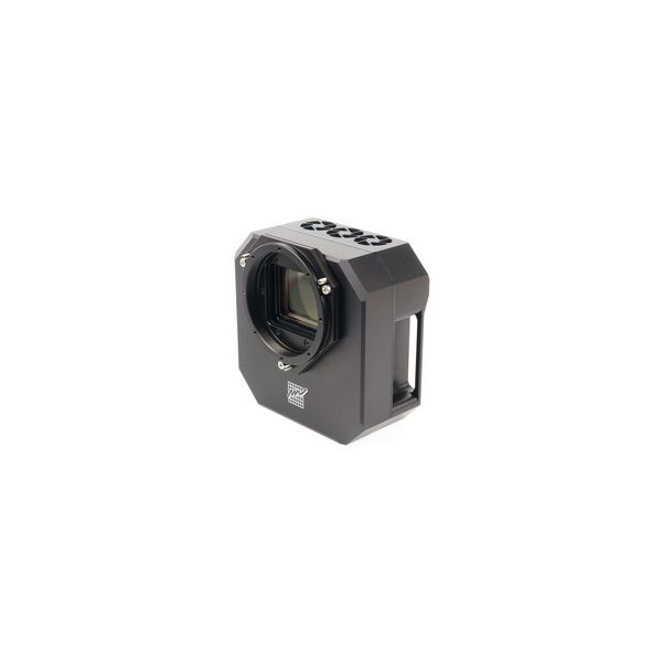
Power supply specification Remark: Power consumption is measured on the 12 V DC side. Power consumption on the AC side of the supplied AC/DC power brick is higher. The camera contains its own power supplies inside, so it can be powered by unregulated 12 V DC power source — the input voltage can be anywhere between 10 and 14 V. However, some parameters (like cooling efficiency) can degrade if the supply drops below 12 V. C5 camera measures its input voltage and provides it to the control software. Input voltage is displayed in the Cooling tab of the Imaging Camera control tool in the SIPS program. This feature is important especially if you power the camera from batteries. 12 V DC/10 A power supply adapter for C5 camera Mechanical SpecificationsCompact and robust camera head measures only 154 × 154 × 76 mm (approx. 6 × 6 × 3 inches). The head is CNC-machined from high-quality aluminum and black anodized. The head itself contains USB-B (device) connector and 4-pin 12 V DC power plug, no other parts, except a “brick” power supply, are necessary. Another connector on the camera head allows control of optional external filter wheel. Integrated mechanical shutter allows automatic dark frame exposures, which are necessary for unattended, robotic setups.
Mechanical specification Camera head front viewC5 camera head interface for filter wheel or tiltable adapter base Filter wheels or tiltable adapter base are attached to the camera head using six M3 screws around the 70 mm diameter ring. Camera with M85 × 1 threaded adapterC5 camera head with M85 × 1 adapter front view C5 camera head with M85 × 1 adapter side view with back focal distance C5 camera with External Filter wheel with M85 × 1 adapter Back Focal Distance The stated back focal distances (BFD) include corrections for all optical elements in the light path (cold chamber optical window, sensor cover glass, ...), fixed in the camera body. So, stated values are not mechanical, but optical back focal distances. However, no corrections for filters are included, as the thicknesses of various filters are very different. Hint: Note the M85 × 1 adapter is also equipped with eight M3 threaded holes arranged around the 91 mm diameter circle. These threaded holes provide alternative mean of camera attachment to the optical system. Camera with M68 × 1 threaded adapterC5 camera head with M68 × 1 adapter front view C5 camera head with M68 × 1 adapter side view with back focal distance (right) C5 camera with External Filter wheel with M68 × 1 adapter Back Focal Distance Filter distance to sensorIt is necessary to know the distance of the filter entrance aperture from the sensor to calculate possible vignetting (partial shielding of the sensor edge parts from the incoming lights). In the case of C5 cameras, this is technically not an “aperture”, as the filters are squares. So, instead of comparing filter aperture diameter to sensor diagonal, filter hole linear dimension must be compared longer side of the sensor. Distance of the filter wheel entrance pupil from the sensor The 7-positions filter wheel for 50 × 50 mm filters entrance dimension is 48 mm, 5-positions filter wheel for 65 × 65 mm filters entrance dimension is 63 mm. The C5A-100M sensor longer side measures 43.86 mm, while the C5A-150M sensor longer side measures 53.42 mm. Optional accessoriesVarious accessories are offered with C5 cameras to enhance functionality and help camera integration into imaging setups. External filter wheelsThe C5 camera contains electronics and an 8-pin connector on the camera head to control filter wheels. As the mechanical interface of the C5 cameras, intended to attach filter wheels, differs from the interface on the C3 or C4 cameras (see the chapter Camera head front view of the Mechanical Specification section for details), C5 cameras are not compatible with the “M” or “L” external filter wheels intended for C3 or C4 lines. New “XL” size external filter wheel is designed especially for the C5 series.
C5 camera with the “XL” filter wheel attached The ”XL” filter wheel housing can accommodate two filter wheels:
Remark: Note the 50 × 50 mm filters are suitable for C5A-100M cameras only, as the filter would partially shade sides of the large sensors of the C5A-150M camera. Telescope adaptersThere are basically only two types of telescope adapters, available for C5 cameras:
Both adapters have adjustable tilt and both can be mounted either on the adapter base on the camera head or on the External filter wheel front plane. Remark: Note the Back Focal Distances of these adapter are slightly different because of differences in mechanical design. BFD also varies for adapter mounted directly on the camera head or on the filter wheel. Refer to the Mechanical Specification chapter for exact BFD values, please. GPS receiver moduleThe C5 cameras can be equipped with an optional GPS receiver module, which allows very precise timing of the exposure times. Geographic location data are also available to the control software through specific commands. There are two variants of available modules:
Both variants are located on the back side of the camera head, between the power and USB connectors. If the camera is not equipped with the GPS module, the GPS port is covered with a flat black cap. GPS receiver module with integrated antennaThe module cover is made from orange plastic to indicate the presence of RF antenna, which needs unobstructed view of the sky to successfully acquire signal from GPS satellites. If the camera is located in the observatory dome, especially if the dome is covered by copper or other metallic sheets, GPS receiver may not be able to capture signal from GPS satellites. Also, if the camera is located on the telescope back side, so the camera back side points mostly to the ground, GPS signal reception can be compromised. The GPS receiver with integrated antenna also can be unable to capture signal from enough satellites when the USB3 connection is used. Please note this issue is not specific to the C5 camera, but it affects any GPS receiver or other RF devices, operating in a close proximity to a USB3 line. Using of USB2 cable solves this problem, but at the expense of slower image download. If the USB3 connection is used, usage of the GPS module with external antenna may be necessary. C5 camera without (left) and with GPS module with integrated antenna (right) GPS receiver module with external antennaThe variant of GPS module with external antenna is attached to the camera head the same way like the previous variant. The module cover is black as it does not need any special handling. The cover is thinner, but there is a connector for the GPS antenna on it. Note the module can work only if the antenna is connected. GPS antenna is shipped with this variant of the GPS module. Antenna cable is 3 m long and the antenna is equipped with a magnet, allowing it to be attached to any ferromagnetic surface. The C5A camera with GPS receiver module with external antenna GPS receiver module handlingBoth GPS receiver module variants are fully software compatible and exchanging one module variant for another does not need any software or driver changes. However, if the GPS module is to be added later, the camera must be sent to manufacturer. Connecting the GPS module to available port is not enough, it is also necessary to reconfigure the camera firmware. GPS module is handled through camera command set. Its main purpose is to provide very precise timing of the exposure times with μs precision (the GPS module provides time pulses with 30 ns tolerance). Geographic location data are also available to the control software through specific commands. The GPS module needs to locate at last 5 satellites to provide exposure timing information. Geographic data are available if only 3 satellites are visible, but especially the mean sea level precision suffers if less than 4 satellites are used. Spare desiccant containersThe C3 cameras are supplied with silicagel container, intended to dry the sensor cold chamber. This container can be unscrewed and desiccant inside can be dried in the oven (see the camera User's Manual). The whole desiccant container can be baked to dry the silica-gel inside or its content can be poured out after unscrewing the perforated internal cap and baked separately Remark: This is why the container itself does not contain any sealing, which could be damaged by high temperature in the owen. The sealing remains on the sensor cold chamber instead. New containers have a thin O-ring close to the threaded edge of the container. This O-ring plays no role in sealing the sensor cold chamber itself. It is intended only to hold possible dust particles from entering the front half of the camera head with the sensor chamber optical window, shutter and possibly internal filter wheel. While the O-ring material should sustain the high temperature during silica-gel baking, it is possible to remove it and put it back again prior to threading the contained back to the camera. Container shipped with the camera by default does not exceed the camera head outline. It is equipped with a slot for tool (or for just a coin), allowing releasing and also tightening of the container. Containers intended for enhanced cooling cameras are prolonged as the camera thickness is greater in the case of this variant. It is possible to order spare container, which makes desiccant replacement easier and faster. It is possible to dry the spare container with silicagel and then only to replace it on the camera. Spare container is supplied including the air-tight cap. Spare container can be supplied also in a variant that allows manipulation without tools. But this container is longer and exceeds camera outline. If the space behind the camera is not critical, this container can make desiccant exchange even easier. Optional cap, standard and tool-less container variants Moravian Camera Ethernet AdapterThe Moravian Camera Ethernet Adapter allows connection of up to 4 Cx cameras of any type on the one side and 1 Gbps Ethernet on the other side. This adapter allows access to connected Cx cameras using routable TCP/IP protocol over practically unlimited distance.
The Moravian Camera Ethernet Adapter device (left) and adapter with two connected cameras (right) Moravian Camera Ethernet Adapter devices are described in detail here. Software SupportPowerful SIPS (Scientific Image Processing System) software, supplied with the camera, allows complete camera control (exposures, cooling, filter selection etc.). Also automatic sequences of images with different filters, different binning etc. are supported. With full ASCOM standard support, SIPS can be also used to control other observatory equipment. Specifically the telescope mounts, but also other devices (focusers, dome or roof controllers, GPS receivers etc.). SIPS also supports automatic guiding, including image dithering. Both “autoguider” port hardware interface (6-wire cable) and mount “Pulse-Guide API” guiding methods are supported. For hi-quality mounts, capable to track without the necessity to guide at last during one exposure, inter-image guiding using the main camera only is available. SIPS controlling whole observatory (shown in optional dark skin) But SIPS is capable to do much more than just camera and observatory control. Many tools for image calibration, 16 and 32 bit FITS file handling, image set processing (e.g. median combine), image transformation, image export etc. are available.
SIPS handles FITS files, supports image calibration and processing As the first “S” in the abbreviation SIPS means Scientific, the software supports astrometric image reduction as well as photometric processing of image series.
SIPS focuses to advanced astrometric and photometric image reduction, but also provides some very basic astro-photography processing SIPS software package is freely available for download from this www site. All functions are thoroughly described in the SIPS User's Manual, installed with every copy of the software. Drivers for ASCOM standard as well as native drivers for third-party software are also available (e.g. TheSkyX, MaxIm DL, AstroArt, etc.). Visit the download page of this web site for current list of available drivers, please. Also INDI drivers for 32 bit and 64 bit Linux running on x86 and ARM are available. Also drivers for TheSkyX package running on macOS are supplied with the camera. Warning: Make sure to always use the latest versions of available software and drivers. Minimal versions or the respective software packages, supporting the C5 cameras, are:
Automatic guidingSIPS software package allows automatic guiding of the astronomical telescope mounts using separate guiding camera. Proper and reliable automatic guiding utilizing the computational power of Personal Computer (e.g. calculation of star centroid allows guiding with sub-pixel precision) is not simple task. Guiding complexity corresponds to number of parameters, which must be entered (or automatically measured). The SIPS “Guider” tool window The “Guiding” tool allows switching of autoguiding on and off, starting of the automatic calibration procedure and recalculation of autoguiding parameters when the telescope changes declination without the necessity of new calibration. Also swapping of the German Equatorial mount no longer requires new autoguider calibration. There is also a graph showing time history of guide star offsets from reference position in both axes. The length of graph history as well as the graph range can be freely defined, so the graph can be adjusted according to particular mount errors and periodic error period length. Complete log of calibration procedure, detected offsets, correction pulses etc. is also shown in this tool. The log can by anytime saved to log file. An alternative to classic autoguiding is the inter-image guiding, designed for modern mounts, which are precise enough to keep tracking with sub-pixel precision through the single exposure, and irregularities only appear on the multiple-exposure time-span. Inter-image guiding then performs slight mount position fixes between individual exposures of the main camera, which eliminates “traveling” of the observed objects through the detector area during observing session. This guiding method uses main imaging camera, it does not use another guiding camera and naturally does not need neither OAG nor separate guiding telescope to feed the light into it. Inter-image guiding controls in the Guiding tab of the Imager Camera tool window Shipping and PackagingC5 cameras are supplied in the foam-filled, hard carrying case containing:
|
| Free Shipping | No |
|---|